Give the drag equation a physical meaning
A common expression for aerodynamic drag is D = ½ρv²CDA. Here D is the resisting force, ρ is air density, v is the train’s speed relative to the air, A is a stated reference area and CD is a drag coefficient defined using that area. The factor ½ρv² is dynamic pressure. It provides a useful scale for aerodynamic loading, not a complete description of the flow.
The coefficient collects the influence of geometry and flow conditions into a non-dimensional value. It is not a permanent material property of a train. Its reported value depends on the reference area and can change with yaw, configuration and test conditions. Two coefficients are not directly comparable until their definitions are aligned. In a crosswind, the relative flow direction also changes, bringing side force and rolling moment into the assessment.
Why the power rises faster than the force
At steady speed, the mechanical power spent overcoming a resisting force is that force multiplied by speed in the direction of motion. In still air, with density, reference area and drag coefficient held constant, aerodynamic drag scales with v² and its associated power scales with v³. This is the origin of the familiar statement that high-speed aerodynamic power grows rapidly with speed. It is a conditional relationship, not a complete train energy model.
For example, increasing speed by 10% gives a drag ratio of 1.1² = 1.21 and an aerodynamic power ratio of 1.1³ = 1.331. The first is a 21% increase; the second is about a 33% increase. On a fixed-distance cruise segment under these assumptions, work against aerodynamic drag scales with v² because work is force multiplied by distance. Do not confuse this journey-segment energy with instantaneous power.
A timetable is more than a cruise condition
A complete journey includes departures, speed restrictions, climbs, coasting and braking. Heating, ventilation and air conditioning consume energy over time, so a shorter journey can change auxiliary consumption even while higher speed raises aerodynamic work. Regenerative braking may return some energy, depending on the vehicle and the network’s ability to receive it. Passenger load and occupancy introduce another distinction between energy per train and energy per passenger.
This is why a lower measured drag coefficient is valuable but does not by itself specify annual energy savings. A credible estimate needs a duty cycle, route profile, operating policy and efficiency assumptions. A design change may also alter mass or cooling requirements. The most useful claim states both the aerodynamic result and the operating scenario used to translate it into energy.
Sound comes from fluctuating flow, not average drag alone
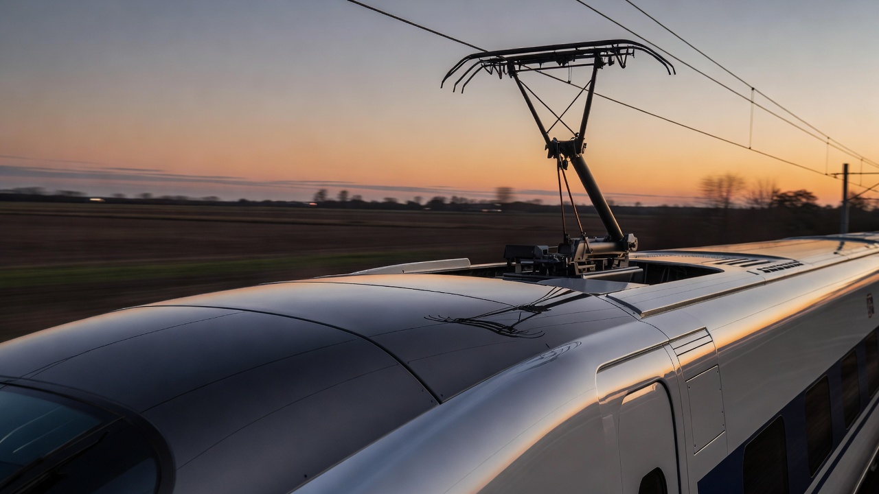
Aerodynamic noise arises from time-varying flow and its interaction with surfaces and edges. Pantographs, bogies, cavities and other exposed components can contribute. Mean drag, by contrast, is an average force resisting motion. The two quantities are related through the flow but are not interchangeable. A geometry can reduce a strong local tone without producing a large change in total resistance, or reduce resistance while leaving a prominent sound source untreated.
Noise also has a frequency distribution, directionality and receiver location. A single level cannot describe every aspect of how an event is heard. Railway sound includes rolling and other mechanical sources as well as aerodynamics; their relative importance varies with speed and configuration. ISO 3095 provides methods for measuring noise emitted by railbound vehicles. A defensible before-and-after comparison must control operating conditions and measurement arrangements.
| Objective | Useful evidence | Possible conflict |
|---|---|---|
| Lower resistance | Force measurements and validated calculations | Added mass, cooling restriction or access difficulty |
| Lower sound | Spectra, levels and source localisation | Another source may become dominant |
| Crosswind resilience | Loads over yaw angles and vehicle dynamics | Zero-yaw drag is not the full objective |
| Lower journey energy | Route-based energy model and service data | Journey time, capacity and auxiliary use |
Crosswind changes the question
In a side wind, the train experiences a resultant airflow at an angle to its length. Pressure becomes asymmetric and produces lateral loads and moments. Those loads must be considered together with vehicle mass distribution, suspension and track conditions. An aerodynamic shape that performs well in straight-ahead flow is not automatically the best shape at yaw. EN 14067-6 addresses requirements and test procedures for crosswind assessment.
Wind barriers and infrastructure can modify exposure, but they can also create transitions and local flow changes. As with tunnels, the operating environment belongs inside the problem definition. The European Union Agency for Railways and the relevant technical specifications for interoperability provide regulatory context; an educational explanation is not a route authorisation or a safety assessment.
Look for a balanced, testable decision
A strong design case identifies an objective, states constraints and reports uncertainty. It compares realistic configurations rather than a bare idealised shape against a fully equipped production train. It also asks whether the improvement survives rain, surface wear, winter operation and maintenance cycles. The result may be a slightly less elegant contour that delivers better whole-life performance.
For your own reading, keep three columns: what changed, what was measured and what stayed constant. Add the source and the intended operating range. That simple discipline prevents the speed-cubed rule, a striking noise plot or a dramatic nose photograph from becoming a conclusion larger than the evidence supports.
- NASA Glenn: the drag equation — definitions of dynamic pressure, drag coefficient and reference area.
- International Organization for Standardization — ISO 3095, railway acoustics measurement methods.
- CEN-CENELEC — EN 14067-6, crosswind assessment.
- European Union Agency for Railways — interoperability and railway regulatory context.